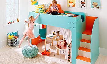
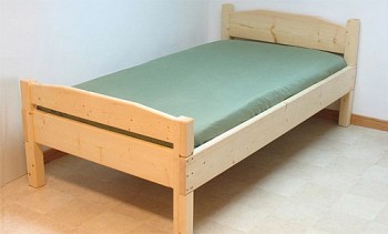
Your child will definitely have sweet dreams if he has a bed stylized as a race car. It is not necessary to go in search of something like this in furniture stores: such a crib bed can be made by the hands of a loving father. Using our tips, you will reach the finish line as soon as possible.

Content:
Appendix - layout and drawings of the car bed
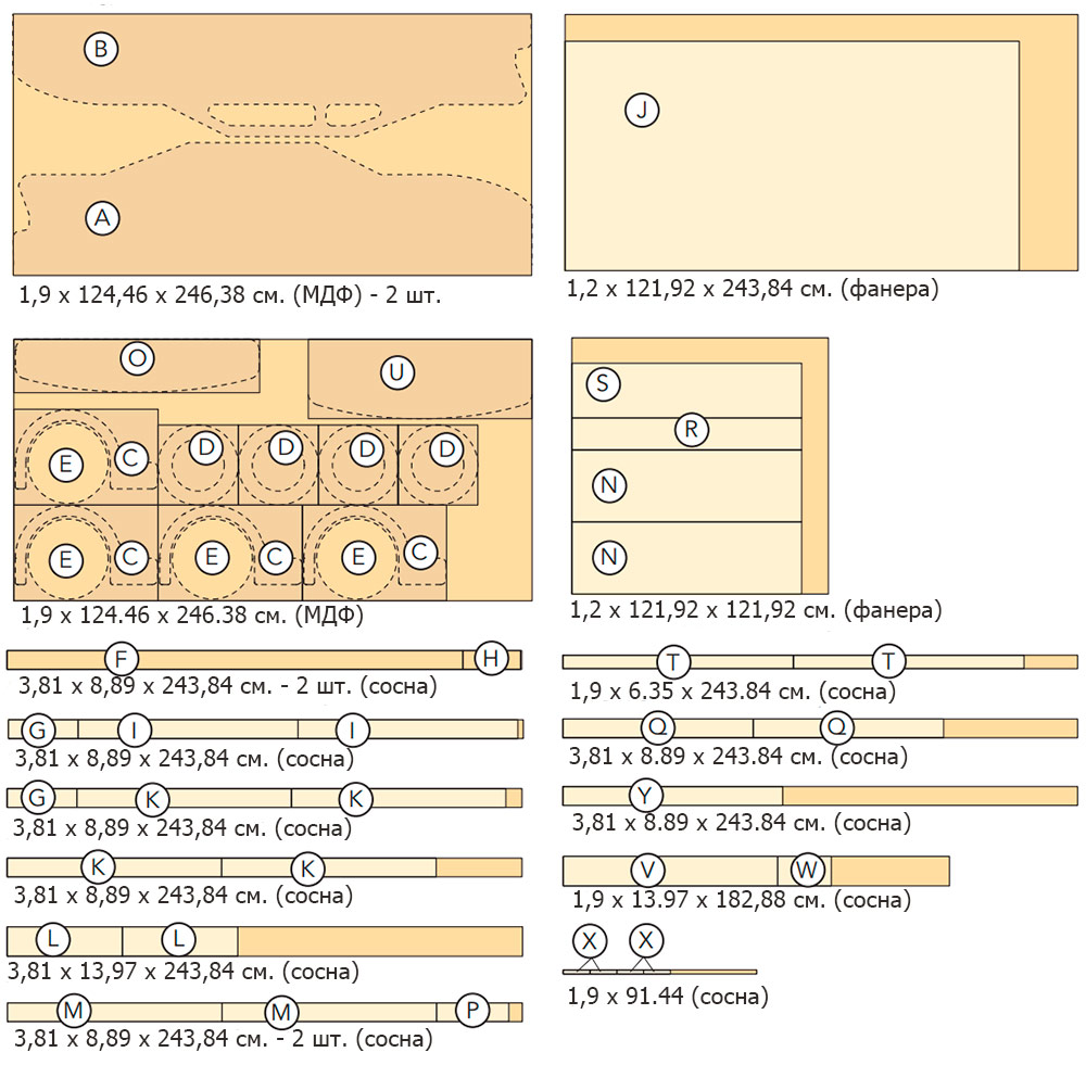
To clearly show how to make a bed a car, first familiarize yourself with the cutting layout and drawings of the entire product. Further in the text, we will return to these details more than once and explain all the moments of its manufacture.
Nesting list
| PC. | Detail | Thickness cm | Width cm | It is long, cm | ||
|---|---|---|---|---|---|---|
| Parties | 2 | A | Side (MDF) | 1,9 | 63,5 | 246,4 |
| 2 | B | Panel with windows (MDF) | 1,9 | 58,4 | 246,4 | |
| 4 | C | Wing (MDF) | 1,9 | 38,1 | 68,6 | |
| 4 | D | Tire (MDF) | 1,9 | 38,1 | 38,1 | |
| 4 | E | Wheel (MDF) | 1,9 | 38,1 | 38,1 | |
| 2 | F | Support block (pine) | 3,8 | 8,9 | 215,9 | |
| 2 | G | Partition (pine) | 3,8 | 8,9 | 34,3 | |
| 2 | H | Seat bars (pine) | 3,8 | 8,9 | 27,3 | |
| 2 | I | Exhaust system (pine) | 3,8 | 8,9 | 104,1 | |
| Base | 1 | J | Base (plywood) | 1,3 | 109,2 | 215,9 |
| 4 | K | Bars (pine) | 3,8 | 8,9 | 101,6 | |
| Spoiler | 2 | L | Side (pine) | 3,8 | 14 | 54,6 |
| 4 | M | Cross member (pine) | 3,8 | 8,3 | 101,6 | |
| 2 | N | Partition (plywood) | 1,3 | 34,3 | 109,2 | |
| 1 | O | Spoiler (MDF) | 1,9 | 25,4 | 116,8 | |
| Seat | 2 | P | Bars for seating (pine) | 3,8 | 8,9 | 34,3 |
| 2 | Q | Seat support bars (pine) | 3,8 | 8,9 | 90,2 | |
| 1 | R | Back (plywood) | 1,3 | 15,2 | 109,2 | |
| 1 | S | Seat (plywood) | 1,3 | 26 | 109,2 | |
| 2 | T | Reiki (pine) | 1,9 | 6,4 | 109,2 | |
| Toy box | 1 | U | Base (MDF) | 1,9 | 38,1 | 106,7 |
| 2 | V | Front / Back (pine) | 1,9 | 14 | 106,7 | |
| 2 | W | Side wall (pine) | 1,9 | 14 | 25,4 | |
| 4 | X | Corner fasteners (pine) | 1,9 | 1,9 | 14 | |
| 1 | Y | Bumper (pine) | 8,9 | 8,9 | 104,1 | |
Nesting pattern
Project outline
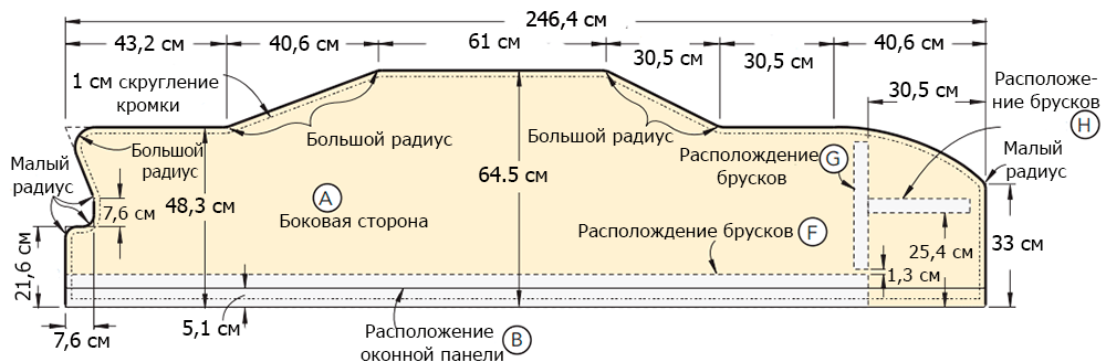
Figure 1 is the side.
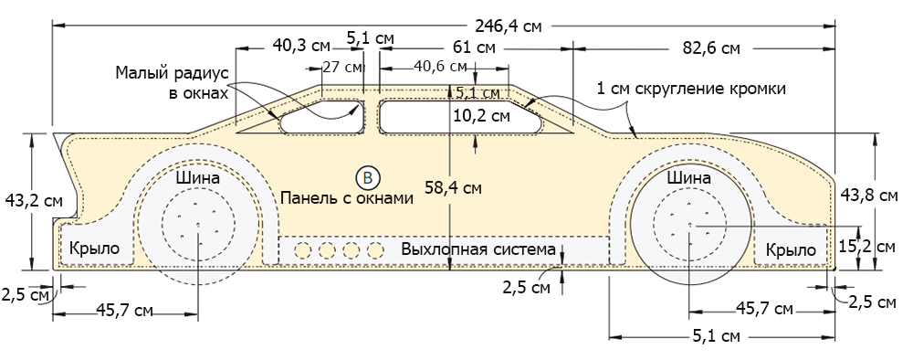
Figure 2 - A panel with windows.

Figure 3 - Wing.

Figure 4 - Bus.

Figure 5 - Wheel.

Figure 6 - Assembly of the side.

Figure 7 - The exhaust system.
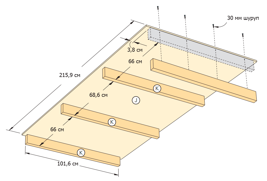
Figure 8 - Base.

Figure 9 - Headboard - side view.
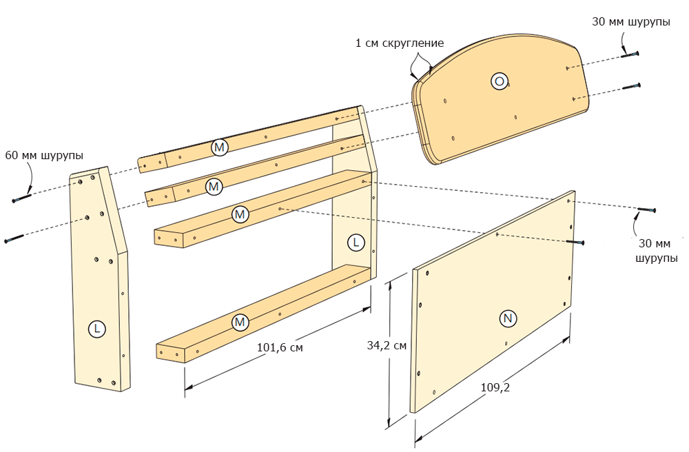
Figure 10 - Headboard.

Figure 11 - Spoiler.

Figure 12 - The back of the seat.

Figure 13 - The lower part of the seat.

Figure 14 - The bottom of the toy box.
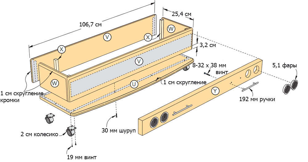
Figure 15 - Assembly of the toy box.

Figure 16 - Bumper.
Bed assembly diagram
The scheme of assembly of the bed No. 1.
Scheme of assembly of a bed No. 2.
We hope that the drawings and photos of the made children's bed-car presented here will help you understand all the intricacies of this project.
Tools and materials
First of all, you should stock up on all the necessary materials and tools (however, any construction project begins with this). Their cost can vary quite a lot depending on the place of purchase, so we will not even try to estimate the cost of the project.
So you will need:
Tools:
- circular or miter saw;
- jigsaw;
- calipers;
- drill;
- bits for twisting screws;
- countersink;
- 5 mm and 10 mm drills;
- 50 mm pen drill;
- eccentric grinding machine with abrasive discs;
- wood file;
- manual milling machine;
- 10 mm nozzle for a milling cutter for a rounding off of corners;
- carpenter's square;
- clamps;
- brush.
Materials:
- lumber (see the list and the cutting scheme in the Appendix);
- 50 mm round ventilation grilles;
- double sided tape;
- two 192 mm nickel bar pulls;
- 6 × 38 mm conical screws with a bolt head (28 pcs.);
- 6 mm washers increased (28 pcs.);
- 10 decorative washers;
- 5 cm furniture castors (4 pcs.);
- 60 mm furniture screws;
- 19 mm pan head screws;
- 25 mm flat head screws;
- 30 mm flat head screws;
- 38 mm flat head screws;
- 50 mm flat head screws;
- 60 mm flat head screws;
- 38 mm screws;
- 10-32 × 38 mm pan head screws;
- wood glue;
- Valspar Signature Paint;
- rags.
Tools and materials are prepared, you can get to work. And we will help you with this.
Side fabrication
Step 1
On a 19 mm thick MDF sheet, draw the outline of the race car (Figure 1 of the Appendix). Sketch the main elements of the car in straight lines: rear and front bumpers, trunk, rear window, roof, windshield, hood.
Step 2
Starting from the rear bumper, give the straight lines of the sketch smoothness, graceful curvature. If necessary, use the objects with a round base of various diameters to draw the curves.

Step 3
To draw a smooth line of the bonnet, use a clamp in the front of the car to easily bend a thin wooden rod and bend it. Draw a pencil line along the resulting arc.

Step 4
Using a jigsaw, cut out the outline of the car. Try to keep the jigsaw blade 1.5-2 mm above the drawn line all the time (photo 3). Sand the edges of the workpiece.

Note: you do not need to strongly strive for accuracy at this stage, small deviations from the line in the order of things - the main thing is that the contour lines of the workpiece are smooth.
Step 5
To process the cut lines, you will need a grinder and a file. For even sections and convex curves, use an eccentric sander with 80 grit sandpaper (photo 4).

Step 6
For concave curves and in narrow spaces, use a file (photo 5). In the final, sand all edges with 120 grit sandpaper.

Step 7
When one side of the car is ready, lay it on the next sheet of MDF and circle the outline. Saw the second side with a jigsaw.
Technique for making copies of parts
Step 1
To make the second side wall, you could cut it with a jigsaw with a small allowance and, using a grinder and a file, bring it to its final shape. But, believe me, this is an extra waste of time. To quickly make the perfect duplicate, use a manual milling machine and a nozzle for edge cladding (photo 6). Use the first, ready-made side wall as a template. We advise you to use this copying method to make duplicates of other parts - body (B), fenders (C), tires (D) and wheels (E).

Step 2
Place the side template (A) on the goats or table, and place a second, roughly cut sidewall on top. Align the factory edges and press the parts together with clamps. Insert a cutter for the edge cladding into the mill and run it along the edge (photo 7). The guide at the bottom of the cutter will follow the pattern, and the milling cutter will trim the edges of the upper, roughly sawn part. As a result, you get the perfect copy of an existing part.

Body panel
Step 1
Now place the template on the rest of the MDF sheet (see Appendix). Slide the bottom edge of the template so that it hangs over the MDF panel by 5 cm (photo 8). Circle the template to get the outline of the body (B) to be cut.

Step 2
Draw window openings (drawing 2 of the Appendix). Use round ventilation grilles with a diameter of 5 cm to make roundings in the corners of the windows (photo 9).

Step 3
To cut the windows, drill a start hole with a diameter of 10 mm, insert a jigsaw blade into it and cut out the mold (photo 10).

Step 4
Use a file to trim the edges of the window openings. Place the panel (B) on the sidewall (A) with a 5 cm bottom offset (Figure 1 of the Appendix). Fasten the parts with clamps and grind the edges of the body panel with a milling cutter (as in making copies of parts).
Step 5
To duplicate the panel (B) for the opposite side of the car, place the finished part on the MDF sheet, align the edges and draw an outline. Saw the workpiece (with a margin) with a jigsaw.
Step 6
Connect the clamp (B) and its copy with the clamps. Use the router to complete the manufacture of the second body panel.
Wings and wheels
Step 1
Draw the contour of the car's wing (C) (Figure 3 of the Appendix). Saw the workpiece with a jigsaw, smooth the edges with a grinder and a file. Use the resulting part as a template to make the remaining three wings.
Step 2
Fasten the narrow parts of the wings laid on each other with a pair of self-tapping screws so that they do not move when milling (photo 11 and 12). The holes left from the screws will later be putty.


Step 3
Draw the bus (D) (Figure 4 of the Appendix). Cut the inside with a jigsaw, having previously drilled the starting hole (photo 13), and then the tire itself (outer contour). Perfect the shape of the tire using a file for the inside circle and a grinder for the outside.

Step 4
Use the made tire as a template for making the rest.
Step 5
Saw four wheels (E) from the MDF (Figure 5 in the Appendix). Plan your location and drill holes for 6 mm diameter bolts.
A little geometry lesson: Each wheel has six bolt holes plus a central hole. Six holes form a regular hexagon. To locate the vertices of this hexagon, draw a circle with a radius of 63.5 mm in the center of the wheel. Then place the compass needle in any point of the drawn circle and draw an arc of the same radius intersecting this circle (photo 14). Move the compass needle to the intersection and repeat the operation. When six points are marked on the circle, you get a regular hexagon.

Step 6
Put the wheel on the tire and fasten them with self-tapping screws (photo 15).

Step 7
Work on the edges of the workpieces to achieve the perfect fit. Repeat for each wheel – tire pair.

Step 8
Number the parts and disconnect the wheels from the tires. Using a special nozzle for the milling cutter, slightly round the edges of all the workpieces (side walls of the bed, body panels, fenders, wheels and tires).
Side wall assembly
Step 1
Before proceeding with painting, it is necessary to partially assemble the structure. Connect the parts with screws and then disconnect again. After you paint the parts, you can assemble them without damaging the paint. For quick final assembly, you just need to screw the screws into existing holes.
Step 2
Saw workpieces for support beams (F), partitions (G), seat base (H) and car exhaust system (I) from a bar with a cross section of 5 × 10 cm (Figure 6 of the Appendix).
Step 3
Lay out sawn bars (F), (G) and (H) on the inner surface of the side wall (A) and secure with double-sided tape (photo 17). Leave enough space between the partition (G) and the support beam (F) to insert the plywood base here later (use a 12 mm cut of plywood to set the correct distance). Turn the MDF over and drill the guide holes for the screws. Now remove the double-sided tape temporarily holding the bars, and finally fix them using glue and screws.

Step 4
Place the body panel in its intended place (Figure 6 of the Appendix) and secure with 30 mm screws and glue. Screw the screws from the side of the side wall (A) as shown in the figure.
Step 5
In a bar intended for the manufacture of the exhaust system (I), drill a hole with a diameter of 50 mm using a feather drill (Figure 7 of the Appendix). Sand the workpiece surface.
Step 6
Turn the side wall over with the body panel up and determine the place where the wings and the exhaust system will be mounted (Figure 2 of the Appendix). Outline the details (photo 18).

Step 7
Fix the wings and the exhaust system with double-sided tape (photo 19). Turn the side wall over and fasten the parts with 50 mm flat head screws (Figure 6 of the Appendix).
Step 8
Repeat all operations for the second side wall.
Tip: To find the place on the back of the panel where you need to drill holes for screws that fix irregularly shaped parts, such as wings, outline them (photos 18 and 19), then remove and drill the guide holes from the front side. Now put the parts on a double-sided tape, turn the assembled assembly over and screw the screws into the wings through the existing holes.
Base
Step 1
Saw the plywood base (J) and the supporting bars with a cross-section of 5 × 10 cm (K) (Figure 8 of the Appendix).
Step 2
Attach the support bars to the plywood base (Figure 8 of the Appendix) with glue and screws.Use a trim of 5 × 10 cm of the bar to set the correct distance from the edge of the base (photo 20).

Spoiler-shaped headboard
Step 1
From boards with a cross section of 5 × 15 cm, make blanks for the sides of the spoiler (L), and from boards with a cross section of 5 × 10 cm - for horizontal elements fastening them (M) (Figures 9 and 10 of the Appendix).
Step 2
Set the upper and front angles of the side walls of the spoiler (Figure 9 of the Appendix); cut off the excess parts with a jigsaw. Sand the parts and assemble the head frame (figure 10 of the Appendix) with glue and 60 mm screws (photo 21).

Step 3
Saw two partitions (N) from 12 mm plywood. Sand the details. Fix the first on the headboard frame, while the second put aside.
Step 4
Saw the spoiler blank (O) from a 19 mm thick MDF. Draw an arc at the top of the workpiece (Figure 11 of the Appendix). To make the arc smooth and symmetrical, use a flexible wooden rod, as you already did, drawing the outline of the hood. In the final round the corners of the drawn arc. Saw the spoiler with a jigsaw, sand the edges.
Step 5
Using a 10 mm milling head, slightly round the front and rear edges of the upper and side edges of the spoiler. Sand the part and attach it to the headboard frame (photo 22). The spoiler should be located symmetrically with respect to the side walls (L), and its lower edge should be flush with the lower surface of the last cross member (M).

Seat
Step 1
Saw the blanks (P) and (Q) from the bar with a cross section of 5 × 10 cm for the seat frame (Figure 12 of the Appendix). From 12 mm plywood, cut out the backrest (R) and the seat (S). Sand the workpieces. Saw the top of the backrest (T) from a 2.5 × 7.5 cm rail.
Step 2
Using screws and glue, connect the elements of the seat frame (P) and (Q) (Figure 12 of the Appendix). Attach the assembled assembly to the remaining partition (N) (photo 23).

Step 3
Using glue and clamps, attach the backrest (R) (photo 24) and the seat (S) (Figure 13 of the Appendix).

Step 4
Attach the remaining block (Q) under the front edge of the plywood seat.
Step 5
Place the rails (T) on the top of the back and front of the seat and secure with glue and clamps. When the glue dries, slightly smooth the edges of the rails using a router with a special nozzle. Sand the surfaces.
Toy box
Step 1
Saw the bottom of the box (U) from a 19 mm thick MDF sheet (Figure 14 of the Appendix). Give its front part a slightly rounded shape. Cut the arc with a jigsaw, sand the edges.
Step 2
Use a router with a special 10 mm nozzle to round the front top edge of the bottom of the toy box. Edges of the sides do not need to be processed.
Step 3
Saw the front / back (V) and side (W) walls of the box from the board with a cross section of 2.5 × 15 cm, and from the bar 2 × 2 cm - corner fasteners (X). Sand the edges of the workpieces.
Step 4
Assemble the toy box (Figure 15 of the Appendix) using glue and clamps (photo 25). Fasten 2 × 2 cm bars to the inside corners of the box.

Step 5
Round the top edges and corners of the drawer using a mill with a 10 mm nozzle. The lower edges do not need to be touched.
Step 6
Sand the surfaces of the box walls and glue them to the bottom. When the adhesive has hardened, remove the clamps and round off the lower corners with a file (photo 26).

Step 7
Saw out the last piece from the 5 × 10 cm bar - the bumper (Y). (You were not mistaken - the word “last” was uttered. So, you are not far from the moment when you make a car bed with your own hands, and your little son will receive the best present in his life.) Using a feather drill, drill holes in it with a diameter 5 cm for headlights (Figure 16 of the Appendix).
Step 8
Attach the handles after pre-drilling holes with a diameter of 5 mm and countersink them from the rear side of the bumper to a depth of 6 mm (these recesses will allow you to recess the screws that secure the handles so that the bumper sits on the front of the box evenly and snugly against it).
Step 9
Fasten the bumper to the toy box by screwing in the screws on the inside.
Painting
Step 1
To prepare for painting, you need to disassemble some nodes. This will greatly facilitate the process. Remove the handles and bumper from the toy box, tires from the wheels, fenders and exhaust systems from the sides of the bed.
Step 2
Pre-coat all elements with a primer.The underside of the bed does not need to be finished.
Tip: Mix water and wood glue in a 1: 1 ratio. This mixture, applied to the edges of the MDF, will clog the pores, which will cover the material with a primer that will not be absorbed into the MDF like a sponge.
Step 3
Paint the details of the bed in accordance with schemes 1 and 2 (see Appendix). Apply two coats of paint on all surfaces and let the paint dry for a week.
Step 4
Reattach the tires to the wheels, fenders and exhaust systems to the sides of the bed. To mount the wheels on the car, center each in the wing and drill the guide holes (through the wheel toward the machine). Now fasten the wheels with 6 × 38 mm conical bolts with bolt head equipped with 6 mm enlarged washers.
Step 5
Place the round ventilation grilles in the openings of the exhaust system, as well as in the openings of the bumper. If necessary, use a wooden block and hammer to push them into place.
Step 6
Install the handles on the bumper and the bumper on the toy box.
Step 7
Turn the toy box upside down and fasten the furniture rollers with the screws. Position the casters so that the mounting plates are ~ 2.5 cm from the edges of the drawer.
Bed installation
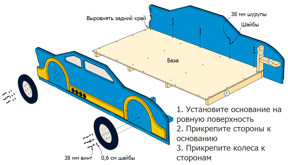
Step 1
Place the base on a fixed bed. Schemes 1 and 2 presented in the Appendix will help you assemble the bed.
Step 2
Slide the sides of the bed onto the base (plywood should slide along the bars attached to the side walls). Align the back of the side walls with the end of the base. Drill guide holes and attach the base to the support beams (F) using # 10 × 38 mm self-tapping screws with washers (Scheme 1 of the Appendix).
Step 3
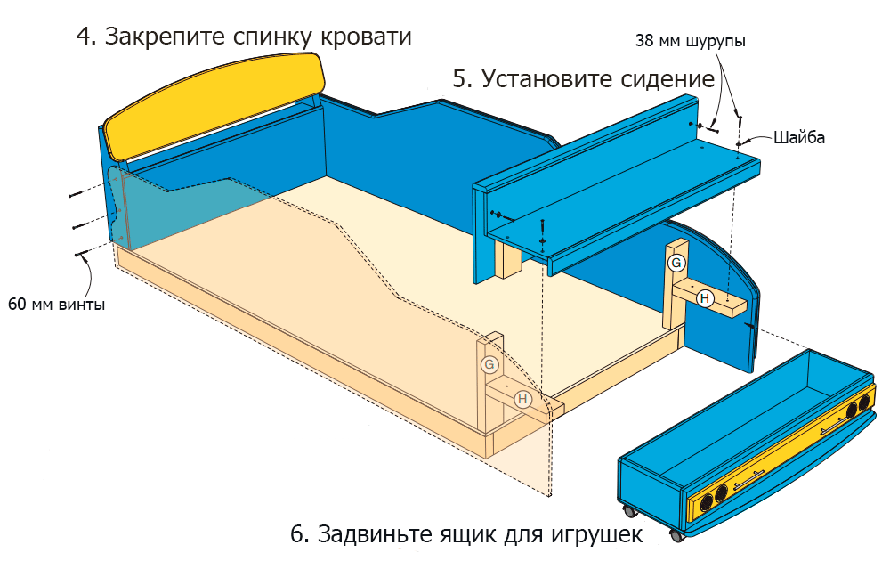
Place the headboard in the place intended for it - the back edge of the headboard should be aligned with the back of the assembled base (Scheme 2 of the Appendix). Fasten the headboard with screws at this stage is not necessary.
Step 4
Install the front seat. It should rest on the bars (H) that are fixed to the side walls.
Step 5
When the seat and headboard are in place, secure them. Screw in three 60 mm furniture screws on each side of the vehicle through the sidewalls at the head. Fix the seat and the back of the seat on the support bars using # 10 × 38 mm self-tapping screws equipped with decorative washers.
Step 6
Slide the toy box under the bench, put a single spring mattress on the bed ... The car bed for your boy is ready! And let the race begin to dream!